3.3.2 GPIO Usage Instructions
Last Version: 10/09/2025
This section explains how to use the Python gpiozero library to control the GPIO pins on the development board. The gpiozero library provides a simple, intuitive API for interacting with buttons, LEDs, servos, and other peripherals.
Reference: Official documentation is available at https://gpiozero.readthedocs.io
Preparation
Before using GPIO, check the pin numbers for your board in Pin Definition Description. This guide uses the MUSE Pi board as an example.
Install the Runtime Environment
You can install gpiozero either system-wide or inside a Python virtual environment.
-
System-wide installation:
sudo apt update
sudo apt install python3-gpiozero -
Virtual environment installation:
source your-venv-path/bin/activate
pip install -i https://git.spacemit.com/api/v4/projects/33/packages/pypi/simple gpiozero
Pin Factory Configuration
gpiozero requires specifying the pin factory at runtime. For best compatibility, it is recommended to use the lgpio library.
Add the following at the start of your Python script:
from gpiozero.pins.lgpio import LGPIOFactory
from gpiozero import Device
Device.pin_factory = LGPIOFactory(chip=0)  # Corresponding configuration:  /dev/gpiochip0
Also set the device node permissions:
sudo chmod a+rw /dev/gpiochip0
Check GPIO Layout
To view the GPIO pin layout:
pinout
Example output (MUSE Pi):
Description        : SpaceMIT Board spacemit k1-x MUSE-Pi board rev 1.1
Revision           : deb002
SoC                : M1-8571
RAM                : 7GB
Storage            : MicroSD/SSD
USB ports          : 2 (of which 2 USB3)
Ethernet ports     : 2 (1000Mbps max. speed)
Wi-fi              : True
Bluetooth          : True
Camera ports (CSI) : 1
Display ports (DSI): 1

,---------------------------------------------------------------.
| ooooooooooooo                                  J24  :
| 1oooooooooooo                                       : |Ethernet1
|     MUSE Pi                                      : |Ethernet2
,--------------------------------------------------------------.

MUSE_Pi:
   3V3  (1) (2)  5V
GPIO52  (3) (4)  5V
GPIO51  (5) (6)  GND
GPIO70  (7) (8)  GPIO47
   GND  (9) (10) GPIO48
GPIO71 (11) (12) GPIO74
GPIO72 (13) (14) GND
GPIO73 (15) (16) GPIO91
   3V3 (17) (18) GPIO92
GPIO77 (19) (20) GND
GPIO78 (21) (22) GPIO49
GPIO75 (23) (24) GPIO76
   GND (25) (26) GPIO50
GPIO Input Example (Button)
This example shows how to detect button presses using GPIO.
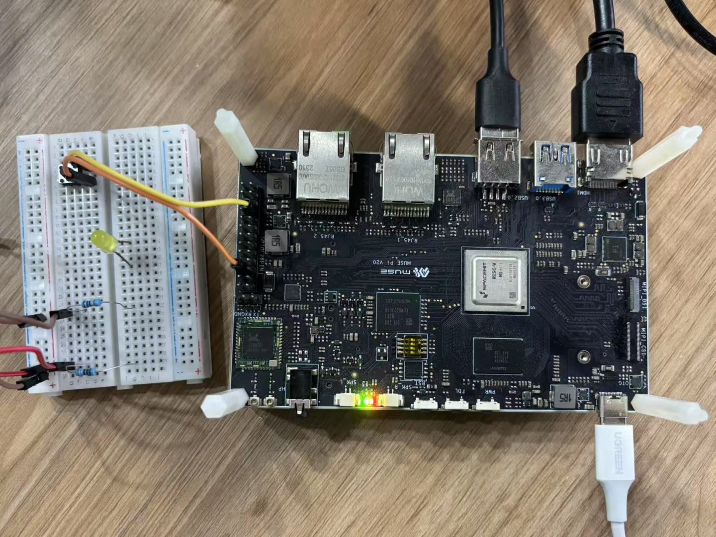
Hardware Connection
Connect the button anode to GPIO 77 and cathode to GND:
Test Code
from gpiozero.pins.lgpio import LGPIOFactory
from gpiozero import Device
Device.pin_factory = LGPIOFactory(chip=0)

from gpiozero import Button
from signal import pause

pin_number = 77
print(f"Monitoring button on GPIO {pin_number}")

def button_pressed():
    print("Button pressed")

def button_released():
    print("Button released")

button = Button(pin_number)
button.when_pressed = button_pressed
button.when_released = button_released

pause()  # Keep the program running
Expected Output After running the program, when pressing and releasing the button:, the terminal will show as below:
Monitoring button on GPIO 77
Button pressed
Button released
GPIO Output Example (LED)
This example shows how to blink an LED using GPIO.
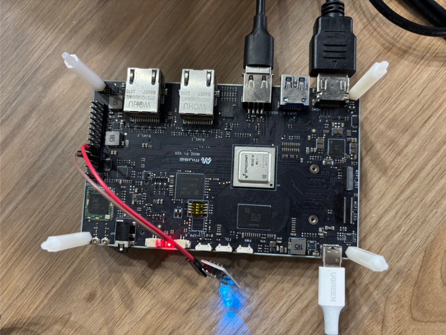
Physical Connection
Connect the anode of the RGB blue LED to GPIO-70, and the cathode to GND through a current-limiting resistor, as shown below:
Test Code
from gpiozero.pins.lgpio import LGPIOFactory
from gpiozero import Device
Device.pin_factory = LGPIOFactory(chip=0)

from gpiozero import LED
import time

pin_number = 70
led = LED(pin_number)

try:
    while True:
        led.on()
        print(f"GPIO {pin_number} ON")
        time.sleep(1)

        led.off()
        print(f"GPIO {pin_number} OFF")
        time.sleep(1)

except KeyboardInterrupt:
    print("\nProgram terminated")
finally:
    led.close()
After you run the program, GPIO 70 switches between high and low every second, making the LED blink. The terminal also prints messages each time the LED changes, for example:
GPIO 70 ON
GPIO 70 OFF
...