3.3.4 I2C Usage Instructions
Last Version: 10/09/2025
This section explains how to use the I²C (Inter-Integrated Circuit) protocol to communicate with peripheral devices on the Bianbu Robot development platform. Examples use Python’s smbus2 library, which is recommended for its compatibility and performance.
Prepare I²C Tools
Clone the I²C debugging tool repository with the following command:
git clone https://gitee.com/cookieee/blue-bridge-cup-hardware.git ~
Tools are located in ~/blue-bridge-cup-hardware/dev-tools/i2ctools, and include the following utilities for detecting and controlling I²C buses:
i2cdetecti2cgeti2cset
I²C Pin Reference
Before wiring any device, check the Pin Definition Document to confirm which pins on your board support I²C.
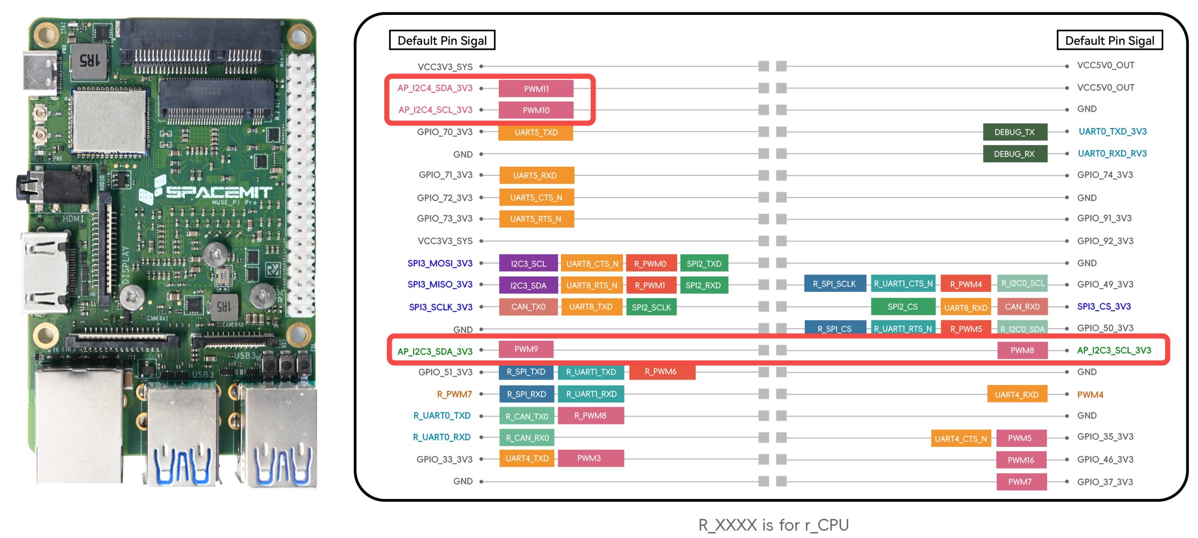
Example: MUSE Pi Pro
- Available buses:
i2c-3andi2c-4 - Pin-out shown below:
Check Available I²C Buses
Navigate to the tool directory and list all detected I²C buses:
cd ~/blue-bridge-cup-hardware/dev-tools/i2ctools
sudo ./i2cdetect -l
Sample output:
i2c-3	i2c       	spacemit-i2c-adapter            	I2C adapter
i2c-1	i2c       	spacemit-i2c-adapter            	I2C adapter
i2c-8	i2c       	spacemit-i2c-adapter            	I2C adapter
i2c-4	i2c       	spacemit-i2c-adapter            	I2C adapter
i2c-2	i2c       	spacemit-i2c-adapter            	I2C adapter
i2c-0	i2c       	spacemit-i2c-adapter            	I2C adapter
i2c-9	i2c       	spacemit-i2c-adapter            	I2C adapter
i2c-5	i2c       	spacemit-i2c-adapter            	I2C adapter
Hardware Connection & Device Scan
Hardware Connection
Connect your I²C peripheral as follows:
| Peripheral Pin | Board Pin |
|---|---|
| SDA | I²C DATA |
| SCL | I²C CLOCK |
| VCC | POWER |
| GND | GROUND |
Scan for Devices
Once connected, scan a specific bus to verify that the device is detected:
sudo ./i2cdetect -yr 4
Parameters:
-ySkip confirmation prompt-rPerform a read-only scan (optional)4Bus number (i2c-4in this example)
Sample output:
     0  1  2  3  4  5  6  7  8  9  a  b  c  d  e  f
00:          -- -- -- -- -- -- -- -- -- -- -- -- --
10: -- -- -- -- -- -- -- -- -- -- -- -- -- -- -- --
20: -- -- -- -- -- -- -- -- -- -- -- -- -- -- -- --
30: -- -- -- -- -- -- -- -- -- -- -- -- -- -- -- --
40: -- -- -- -- -- -- -- -- -- -- -- -- -- -- -- --
50: -- -- -- -- -- -- -- -- -- -- -- -- -- -- -- --
60: -- -- -- -- -- -- -- -- 68 -- -- -- -- -- -- --
70: -- -- -- -- -- -- -- --
A valid device is detected at address 0x68.
Example: Control Devices with Python
It is recommended to use the smbus2 library. Install it with:
pip install smbus2
The following example demonstrates how to read device register data via Python:
from smbus2 import SMBus

bus_number = 4           # Corresponds to i2c-4
device_address = 0x68    # Device address
register_address = 0x00  # Register address

with SMBus(bus_number) as bus:
    data = bus.read_byte_data(device_address, register_address)
    print(f"Value read from register {register_address:#02x}: {data:#02x}")
Please make sure that the I2C device node has read and write permissions:
sudo chmod a+rw /dev/i2c-4
Sample output:
Value read from register 0x00: 0xCF
Important Notes
- Each I²C device on a bus must have a unique address to prevent conflicts.
- Some peripherals require initialization or configuration — refer to the datasheet for details.
- Use
smbus2instead of the legacysmbuslibrary for better performance and compatibility.